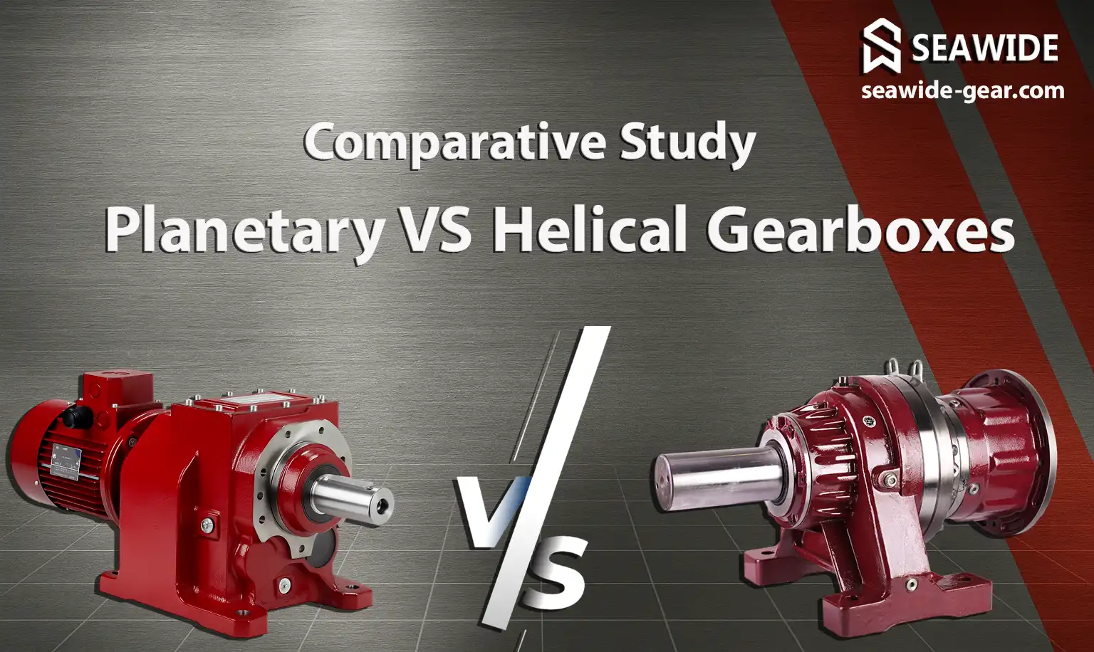
Planetary vs Helical Gearboxes: The Definitive Engineering Guide
Introduction – The Critical Role of Gearbox Selection in Modern Industry
For the modern industrial engineer, the automation revolution is not defined solely by the sophistication of PLCs or the speed of servo motors; it is fundamentally limited—or enabled—by the efficiency and reliability of mechanical power transmission. In an era where operational efficiency translates directly to competitive advantage, and where machine uptime is measured in thousands of dollars per hour, the choice of a gearbox transcends simple component selection. It is a strategic decision that dictates machine performance envelopes, energy consumption profiles, long-term maintenance costs, and overall system reliability.
Within the vast landscape of mechanical components, two technologies dominate the conversation for high-performance industrial power reduction: the compact, torque-dense planetary gearbox and the robust, high-efficiency helical gearbox. These devices are the unsung heroes of industry, silently translating the high speed and low torque of electric motors into the precise speed and high torque required by pumps, mixers, conveyors, robotic arms, and CNC axes.
The fundamental difference between selecting a planetary solution versus a helical solution is the difference between maximizing power density within constrained spatial limits and optimizing for continuous, high-throughput reliability across large mechanical systems. This article serves as the definitive, engineering-grade comparison. We will dissect the mechanics, compare the performance metrics, analyze the trade-offs across critical parameters, and provide a systematic selection guide to empower you—the engineer or industrial manager—to make the optimal choice for your specific application.
We recognize that many manufacturers offer solutions, but for specialized, high-demand applications where failure is not an option, partnering with experts is crucial. Companies like Seawide Gear have built their reputation on providing advanced gearbox solutions, particularly mastering the complex metallurgy and machining required for world-class planetary systems, ensuring that precision and durability go hand-in-hand.
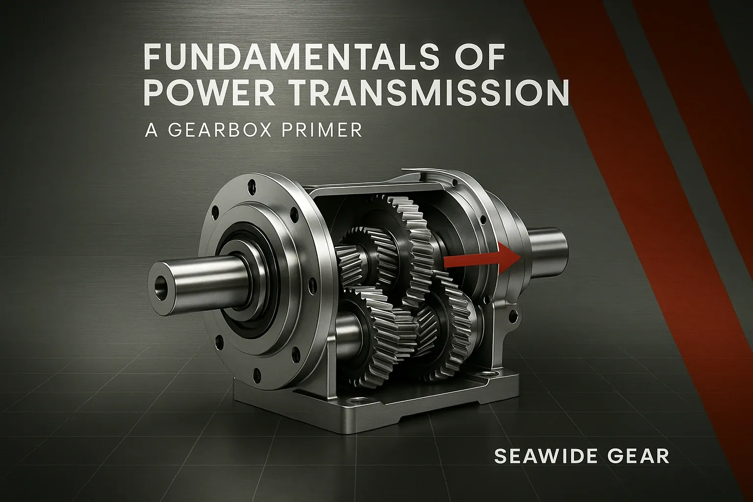
Fundamentals of Power Transmission: A Gearbox Primer
Before embarking on the detailed comparison between planetary and helical configurations, it is essential to establish a common lexicon based on the core engineering principles governing all industrial gear reducers. A gearbox, fundamentally, is a mechanical device designed to manage the relationship between speed and torque between a prime mover (like an AC motor or a servo motor) and the driven machine component.
What is an Industrial Gearbox?
An industrial gearbox functions as a mechanical transformer. Its primary role is to modify the output characteristics of the input shaft to meet the demands of the load. Motors are generally designed to operate most efficiently at high speeds (e.g., 1,500 to 3,000 RPM). However, most industrial processes require significantly lower speeds (e.g., 10 to 500 RPM) coupled with commensurately higher torque to overcome inertia, friction, and process resistance. The gearbox achieves this transformation via the principle of leverage applied to rotating components.
Key Engineering Concepts
Mastering gearbox specification requires a firm grasp of several interconnected concepts:
Gear Torque
Torque (τ), often referred to as “twisting force,” is the rotational equivalent of linear force. In mechanical engineering, torque is the key parameter that determines whether a machine can effectively drive its intended load.
It is calculated as the force applied multiplied by the perpendicular distance from the axis of rotation (the moment arm).
For a gearbox, the core function is transmitting and amplifying torque. The theoretical relationship between input torque, output torque, and gear ratio is defined as:
Output Torque = Input Torque × Gear Ratio × Efficiency
This equation highlights why torque capability is the primary metric when sizing a gearbox.
Gear Ratio (i)
The gear ratio defines how much speed reduction (or increase) the gearbox provides. For standard reduction applications, the ratio is expressed as:
Gear Ratio = Input Speed (RPM) ÷ Output Speed (RPM)
A 10:1 ratio means the output shaft rotates ten times slower than the input shaft — and, ignoring efficiency, the output torque is theoretically ten times greater than the input torque.
For multi‑stage gearboxes, the overall reduction ratio equals the product of the individual stage ratios.
- Impact on Energy Costs: A difference between 92% and 98% efficiency across millions of operating hours translates into significant electricity savings.
- Heat Generation: The lost energy (typically 2% to 8% per stage) is converted into waste heat, which necessitates adequate lubrication and potentially external cooling to maintain lubricant viscosity and prevent premature component wear.
Backlash (Clearance)
Backlash is the small, measurable clearance or “play” between adjacent gear teeth when the direction of rotation is reversed, or when torque is suddenly applied or removed.
It is usually quantified as rotational play, expressed in arc‑minutes or degrees.
Engineering Definition (Plain Text):
Backlash (θ B) = Angular clearance between gear teeth when direction reverses.
Criticality
- In simple motion systems—such as conveyors or material feeders—a moderate level of backlash is acceptable and does not affect operation.
- In high‑precision motion control systems (indexing tables, robotics, CNC cutting tools), excessive backlash leads to position overshoot, vibration, and measurement error, ultimately reducing product accuracy and finish quality.
- Precision planetary gearboxes are engineered to minimize backlash and typically achieve clearance values below 3 arc‑minutes, ensuring excellent repeatability and smooth, responsive performance.
Service Factor (SF)
The Service Factor is a multiplier applied to the required output torque that accounts for the expected duty cycle, shock loading, and operational environment.
It acts as a safety buffer to ensure the gearbox operates reliably and doesn’t fail prematurely under non‑ideal conditions.
Formula (plain text):
Required Rated Torque = Peak Operating Torque × Service Factor
According to AGMA (American Gear Manufacturers Association) standards, the Service Factor varies depending on application type — for example:
- Light‑duty service: continuous smooth loads (fans, conveyors)
- Medium‑duty service: moderate shocks, variable loads (mixers, packaging lines)
- Heavy‑duty service: severe shock loads or impact conditions (crushers, mills)
A properly selected gearbox will therefore have a rated torque capacity significantly higher than its nominal operating torque, guaranteeing longer service life and robustness in industrial environments.
Deep Dive into the Planetary Gearbox (Epicyclic Gear Train) in thePlanetary vs Helical Gearboxes Analysis
The planetary gearbox, known formally as an epicyclic gear train, represents the pinnacle of power density in mechanical speed reduction. Its unique geometry allows it to concentrate a substantial amount of power transfer capability within a remarkably small cylindrical volume.

Operating Principle: The Architecture of Power Sharing
The beauty of the planetary gearbox lies in its internal arrangement, which is analogous to a solar system, hence the common nomenclature:
- Sun Gear (Central Gear): This is the input member (or sometimes the output member). It is centrally located and meshes with the planet gears.
- Planet Gears (Satellite Gears): Typically three or four gears that mesh with both the sun gear and the ring gear. These gears are mounted on a structure called the planet carrier.
- Planet Carrier: This component holds the planet gears and dictates the relative angular position of the planets. The carrier often serves as the input or output component.
- Ring Gear (Annulus): This is the outermost component, featuring internal gear teeth that mesh with the outer periphery of the planet gears. The ring gear is often held stationary (the housing) or serves as the output component.
The fundamental principle enabling the planetary gearbox’s high performance is load sharing. Unlike a parallel-shaft gearbox where the entire torque must be transmitted through the contact point of two meshing gears, the load in a planetary set is distributed across multiple planet gears (usually three or four) simultaneously. This distributed load transfer is the direct mechanism responsible for its superior torque density.
If a simple two-gear mesh can transmit torque (T), a planetary set with (N) planet gears can theoretically transmit (N \times T), provided the load sharing is perfectly balanced—a state closely approximated in high-quality, precision-machined units.
Key Advantages of Planetary Gearboxes
The architectural design of the epicyclic gear train yields inherent advantages highly sought after in advanced machinery:
Exceptional Torque Density
This is the hallmark advantage. Because the load is divided among the multiple planet gears, any single gear within the set is subjected to only a fraction of the total output torque. This allows the entire gearbox to be manufactured with smaller, lighter components relative to the amount of torque it can handle, leading to an extraordinary power-to-weight ratio.
Compact Footprint and Low Weight
The coaxial alignment of the input, intermediate, and output shafts is critical. The input (sun), intermediate reduction stages (planets/carrier), and output (ring/carrier) all share the same axis of rotation. This in-line configuration eliminates the need for complex offsets or external gearing required in many parallel-shaft setups, resulting in a compact, cylindrical housing perfect for installation within tight machine frames or robotic joints.
High Efficiency
Planetary systems utilize predominantly pure rolling contact between the gears. While some sliding friction occurs where the gear teeth profile changes curvature, the overall energy loss due to friction is often comparable to, or slightly better than, multi-stage spur gear systems when operating under optimal lubrication. High-precision planetary gearboxes routinely exceed 96% efficiency per stage.
High Torsional Stiffness and Low Backlash
The inherent structural rigidity provided by the fully enclosed, internally constrained geometry results in high torsional stiffness. Furthermore, the precise preloading mechanisms applied during assembly (often involving specialized bearings and tight tolerances on the ring gear) ensure that backlash is minimized. This stiffness and low backlash are non-negotiable requirements for dynamic precision applications.
Design Configurations
Planetary gearboxes are highly versatile in their mounting arrangements:
- Inline Planetary Gearboxes: The classic configuration where the input and output shafts are collinear. Ideal when shaft alignment is paramount.
- Right-Angle Planetary Gearboxes: Achieved by integrating a bevel gear set at the input stage or utilizing a specialized cross-shaft carrier design. These are crucial when an in-line configuration is physically impossible due to structural constraints.
Materials and Manufacturing
Achieving the stated torque density and low backlash of a premium planetary gearbox demands stringent manufacturing quality:
- Gear Hardening: Gears must be subjected to case hardening (carburizing) followed by precise grinding (e.g., profile ground) or precision honing. This process creates a hard, wear-resistant outer layer (the case) while retaining a tough, ductile core, allowing the gears to absorb high shock loads without catastrophic fatigue failure.
- Tolerance Stacking: Since multiple stages often stack within the same housing, tolerance control across all components—gears, carriers, shafts, and housing bores—is extremely tight to ensure that the cumulative error does not exceed acceptable backlash limits.
Planetary Gearbox Supplier | Gearbox for Sale & price-SEAWIDE
Deep Dive into the Helical Gearbox| Understanding Its Role in the Planetary vs Helical Gearboxes Debate
The helical gearbox, utilizing gears with teeth cut at an angle to the axis of rotation, is perhaps the most common and time-tested industrial speed reducer. While historically overshadowed by the planetary gearbox in discussions of cutting-edge density, the helical design remains the backbone of countless heavy-duty and continuous-operation machinery due to its inherent robustness and operational characteristics.
Operating Principle: Gradual Engagement
Helical gears fundamentally differ from spur gears (whose teeth are parallel to the axis of rotation) by employing a helix angle ((\beta)), typically ranging from 15° to 45°.
When two helical gears mesh, the contact between the teeth begins gradually at one end of the he lix and progressively spreads across the entire face width as the gears rotate. This gradual engagement contrasts sharply with the instantaneous, full-face contact experienced by spur gears.
This progressive loading minimizes the shock load transmitted through the mesh, leading directly to the defining characteristics of helical systems: smoother operation and reduced noise.
Key Advantages of Helical Gearboxes
The physics of the helical tooth profile translate into several significant industrial advantages:
High Efficiency (Especially Single-Stage)
A well-designed, single-stage helical gearbox with ground gears can achieve efficiencies rivaling or even slightly exceeding those of planetary sets (often reaching 98-99% if friction losses are minimized). The primary loss mechanism in helical systems often relates to the sliding component introduced by the helix angle, but this is generally well-managed.
Quiet and Smooth Operation (Low NVH)
This is the most celebrated benefit. Because the load is introduced gradually across the face width, the transmission of force is continuous rather than impulse-based. This drastically reduces the airborne noise (Noise, Vibration, and Harshness – NVH) generated by the gearbox, making them the preferred choice in environments where noise pollution is a concern (e.g., food processing, residential area adjacent facilities).
High Load Capacity
Helical gears offer a higher contact ratio (the average number of tooth pairs in contact) compared to spur gears. This higher ratio effectively distributes the load over a larger cumulative area, allowing a helical gearbox housing to safely manage significantly higher continuous load ratings than a spur gear set of comparable size.
Versatility and Proven Reliability
The design is mechanically straightforward, utilizing well-understood principles of power transfer. This simplicity often translates to reduced manufacturing complexity (compared to stacked planetary elements) and exceptional long-term reliability in steady-state applications.
Design Configurations
Helical gearboxes are configured to meet varied spatial and mechanical mounting requirements:
- Parallel-Shaft Helical Gearboxes: The most common configuration where the input and output shafts run parallel to each other. These form the basis of standard industrial gear reducers and motor reducers.
- Bevel-Helical Gearboxes: Used when a 90-degree change in direction is required. They combine the high efficiency and smooth operation of helical gears on the parallel axis with the right-angle transmission provided by the bevel gear stage.
- Shaft-Mounted Helical Gearboxes: Designed specifically for direct mounting onto the driven shaft, eliminating the need for base plates, couplings, and precise alignment checks. A torque arm anchors the gearbox housing to the nearest fixed structure.
Considerations: Axial Thrust Management
A critical design consideration for any helical system is the generation of axial thrust. Because the teeth are cut at an angle, the contact force vector has a component directed parallel to the shaft axis. This unwanted thrust force must be managed. High-quality helical gearboxes use robust, oversized tapered roller bearings or heavy-duty deep-groove ball bearings specifically designed to absorb these significant axial loads, converting them into radial forces that the main radial bearings can handle. Failure to adequately manage axial thrust is a common cause of premature bearing failure in under-specified helical units.
Planetary Gearbox Supplier | Gearbox for Sale & price-SEAWIDE
Head-to-Head: Planetary Gearbox vs. Helical Gearbox – A Comprehensive Comparison
Engineering Parameter | Planetary Gearbox (Epicyclic) | Helical Gearbox (Parallel/Bevel) | Comparative Winner / Trade‑Off
Torque Density & Footprint | Superior — load sharing enables maximum torque in minimal volume. | Inferior — requires larger diameter and length for equivalent torque. | Planetary: undisputed leader for compact, high‑torque applications.
Precision & Backlash | Excellent — designed for extremely low backlash (≤ 3 arc‑minutes) via preloading and tight tolerances. | Good to moderate — typically higher inherent backlash; precision models exist but more complex. | Planetary: essential for servo control, robotics, and indexing.
Efficiency (Per Stage) | Very high (95% to 97%) — excellent rolling contact. | Very high (95% to 98%) — single stages can be slightly higher due to fewer meshes. | Tie / slight edge to Helical: depends on lubrication and number of stages.
Noise, Vibration, Harshness (NVH) | Moderate to high — load changes abruptly across few planet meshes, generating noise peaks. | Superior — gradual tooth engagement ensures smoother, quieter operation. | Helical: better suited for low‑noise environments.
Ratio Flexibility | Superior — high ratios (up to 100:1) achievable in 3 to 4 compact stages. | Moderate — needs 4 to 6 stages for very high ratios, increasing length. | Planetary: ideal for extreme speed reduction in minimal length.
Heat Dissipation | Fair — smaller external surface area relative to power density; needs effective cooling and lubrication under heavy loads. | Good — larger housing area supports efficient passive heat dissipation. | Helical: easier thermal management for continuous operation.
Initial Purchase Cost | High — complex geometry and precision grinding raise unit cost. | Low to moderate — simpler structure allows economical mass production. | Helical: cost‑effective choice for non‑critical, steady‑state loads.
Complexity & Maintenance | Moderate complexity — multiple planets and carrier system; requires specialized disassembly and reassembly. | Lower complexity — fewer, larger distinct components; easier servicing. | Helical: simpler design means easier maintenance access.
Detailed Analysis of Trade-Offs
Torque Density & Footprint: The Planetary Advantage
The comparison on size is stark. A high-precision planetary gearbox designed for a 20 Nm output at 10 arc-min backlash might occupy a volume of (100 \text{ cm}^3). To achieve the same torque using a parallel-shaft helical gearbox would require a significantly larger, elongated housing to accommodate the two larger gears necessary to handle the full load on a single mesh. For robotics (where every gram and millimeter counts) or machine tool spindles, this difference is decisive.
Precision: The Servo Requirement
When specifying gearboxes for dynamic systems driven by servo motors—where position tracking must be maintained with sub-degree accuracy—backlash is the dominant enemy. The planetary gearbox structure, with its inherent mechanical locking (the ring gear constraining the planets), allows for the precise arrangement of bearings and tooth profiles necessary to achieve backlash figures often under 5 arc-minutes, a level rarely matched economically by helical designs.
Cost vs. Total Cost of Ownership (TCO)
The immediate cost comparison favors the helical gearbox significantly, especially for standard reduction ratios (e.g., 10:1, 20:1). However, an astute engineering manager must look beyond the purchase price to the Total Cost of Ownership (TCO).
If a helical gearbox running at 94% efficiency is chosen over a planetary gearbox running at 97% efficiency in an application running 24/7, the 3% energy loss compounded over five years of operation can easily exceed the initial price difference between the two units. The planetary gearbox, despite its higher capital cost, often delivers a superior TCO in high-utilization, high-precision scenarios.

Real‑World Applications: Where Planetary vs Helical Gearboxes Choices Matter Most
The theoretical comparison must be validated by real-world industrial deployment. The application dictates the requirements, and the requirements point directly toward the appropriate technology.
Robotics, Automation, and CNC Machinery: Planetary Domination
This sector mandates extreme precision, high dynamic response, and the smallest possible moving mass.
- Requirement: High torque output from a lightweight, rotating assembly (e.g., a robotic arm joint). Low backlash is paramount for path accuracy.
- Solution: Planetary Gearboxes. Precision planetary gear sets, often integrated directly into the structural link, provide the necessary stiffness and accuracy for path control. Their coaxial nature allows for direct coupling to servo motors without requiring complex offset mechanisms that would introduce mechanical error or additional inertia.
Steel Mills, Mining, and Heavy-Duty Presses: Planetary’s Strength in Extreme Torque
While often requiring robust housings, these applications demand peak torque handling capability to manage high inertia starts and significant shock loads during material processing (e.g., rolling, stamping).
- Requirement: Continuous high torque transmission with the capacity to absorb substantial, sporadic impact or shock loads. Space constraints might be less severe than robotics, but sheer robustness is key.
- Solution: Heavy-Duty Planetary Gearboxes. These utilize high-strength alloy steels, thicker casings, and specialized lubrication systems. The load-sharing mechanism prevents any single tooth from being overloaded during a shock event, making them exceptionally reliable under punishing conditions where traditional gearboxes might fracture a tooth.
Conveyors, Agitators, and General Material Handling: Helical’s Home Turf
For continuous, steady-state speed reduction where the load profile is relatively smooth, the economic and operational benefits of helical drives are clear.
- Requirement: Reliable, cost-effective speed reduction for moderate loads, often requiring easy installation onto existing shafts. Noise is a secondary, but welcome, consideration.
- Solution: Shaft-Mounted and Parallel-Shaft Helical Gearboxes. Their ease of installation (especially shaft-mounted units that clamp directly onto the conveyor drive shaft) and lower initial cost make them the default choice for general industrial movement applications. Their inherent smoothness also makes them excellent for applications like bulk material agitation where minimizing vibration transferred back to the structure is beneficial.
Wind Turbines: Planetary in a Key Role
Modern utility-scale wind turbines present one of the most demanding torque challenges in the world.
- Requirement: Taking the high-speed output from the rotor hub (relatively low torque, but massive size) and stepping it down through multiple stages to drive the generator. Space within the nacelle is severely limited, and the torque is astronomical.
- Solution: Planetary Gearboxes. The main gearbox connecting the low-speed shaft to the high-speed shaft almost universally incorporates a massive, multi-stage planetary system. This is the only geometry capable of transmitting megawatt-level torque within the tight confines of the turbine nacelle while maintaining the necessary input/output alignment.
Packaging and Printing Machinery: A Mix of Precision and Power
These machines often involve high-speed indexing, intermittent motion, and precise registration.
- Solution: Planetary Gearboxes are used for the precision indexing mechanisms and synchronized transfer points requiring low backlash. Helical Gearboxes (often small, integrated parallel-shaft units) are used for the main bulk power transmission to ancillary systems, offering reliable speed reduction where position accuracy is less critical than throughput.
Engineering Selection Guide in the Planetary Gearbox vs Helical Gearbox Context — How to Specify the Right Model
Selecting the correct industrial gear reducer is a systematic process that connects application requirements with mechanical capability.
Rushing this process can cause premature failure, excessive maintenance, or costly over‑specifying.
Define Your Load and Duty Cycle (The Torque Calculation)
The first and most critical step is to quantify the required output torque at the desired output speed.
- Determine Required Output Speed (ω out): based on the driven process (for example, conveyor belt speed or pump flow rate).
- Calculate Required Input Speed (ω in):If a specific gear ratio is desired,Input Speed = Output Speed × Gear Ratio.If the motor speed is fixed, compute the resulting output speed accordingly.
- Calculate Nominal Output Torque (τ nominal):Derived from load requirements using the standard formula:Nominal Torque = 9550 × Power (kW) ÷ Output Speed (RPM)where Power (kW) is the continuous power demanded by the load.
- Identify Peak and Shock Loads:Assess maximum torque spikes during startup, emergency stop, or sudden load changes (like plugging a conveyor).
Planetary Gearbox Supplier | Gearbox for Sale & price-SEAWIDE
Calculate Required Service Factor (Duty Cycle Application)
Apply an appropriate Service Factor (SF) according to load severity defined in Step 1 and refer to industry standards (AGMA or ISO 6336).
Required Rated Torque = Nominal Torque × Service Factor
This value represents the minimum torque rating the gearbox should provide per manufacturer specifications.
For frequent reversing, heavy start/stop cycles, or impact loads, a higher Service Factor is essential to avoid early fatigue.
Determine Precision Requirements (Backlash Tolerance)
This step defines two distinct paths:
- When positioning accuracy matters (servo‑driven or indexing systems):Backlash should be specified in arc‑minutes.If the required backlash is 10 arc‑minutes or less, a Planetary Gearbox is generally preferred.
- When continuous torque determines position (for bulk conveying or constant‑speed drives):Backlash up to around 30 arc‑minutes can be acceptable.In this range, a Helical Gearbox often provides superior smoothness and reliability.
Analyze Space and Mounting Constraints
Physical installation parameters may outweigh performance metrics.
- Inline Requirement:If the motor axis must align with the load axis, choose a Planetary inline gearbox or specialized parallel‑shaft helical reducer.
- Space Constraint:When axial length must be minimal yet torque maximized, Planetary Gearbox design is ideal because of its radial compactness.
- Right‑Angle Requirement:If shafts cross at 90 degrees, compare Bevel‑Helical versus Right‑Angle Planetary options, assessing efficiency and backlash at that geometry.
Consider Total Cost of Ownership (TCO)
The final step merges initial cost with lifetime cost.
- Capital Cost: initial purchase price of the gearbox.
- Energy Cost: calculate yearly operational hours and apply known efficiencies—typically Planetary ≈ 96%, Helical ≈ 98%—to estimate energy loss per year.
- Maintenance and Downtime: account for service intervals and parts replacement.A high‑quality planetary gearbox lasting 15 years with zero intervention yields far lower TCO than a lower‑tier helical model needing bearing replacement every 5 years.
If the planetary gearbox offers even a 1–2% efficiency and higher torsional stiffness, paying 20–40% more upfront generally results in lower lifetime cost for high‑duty cycles and demanding environments.
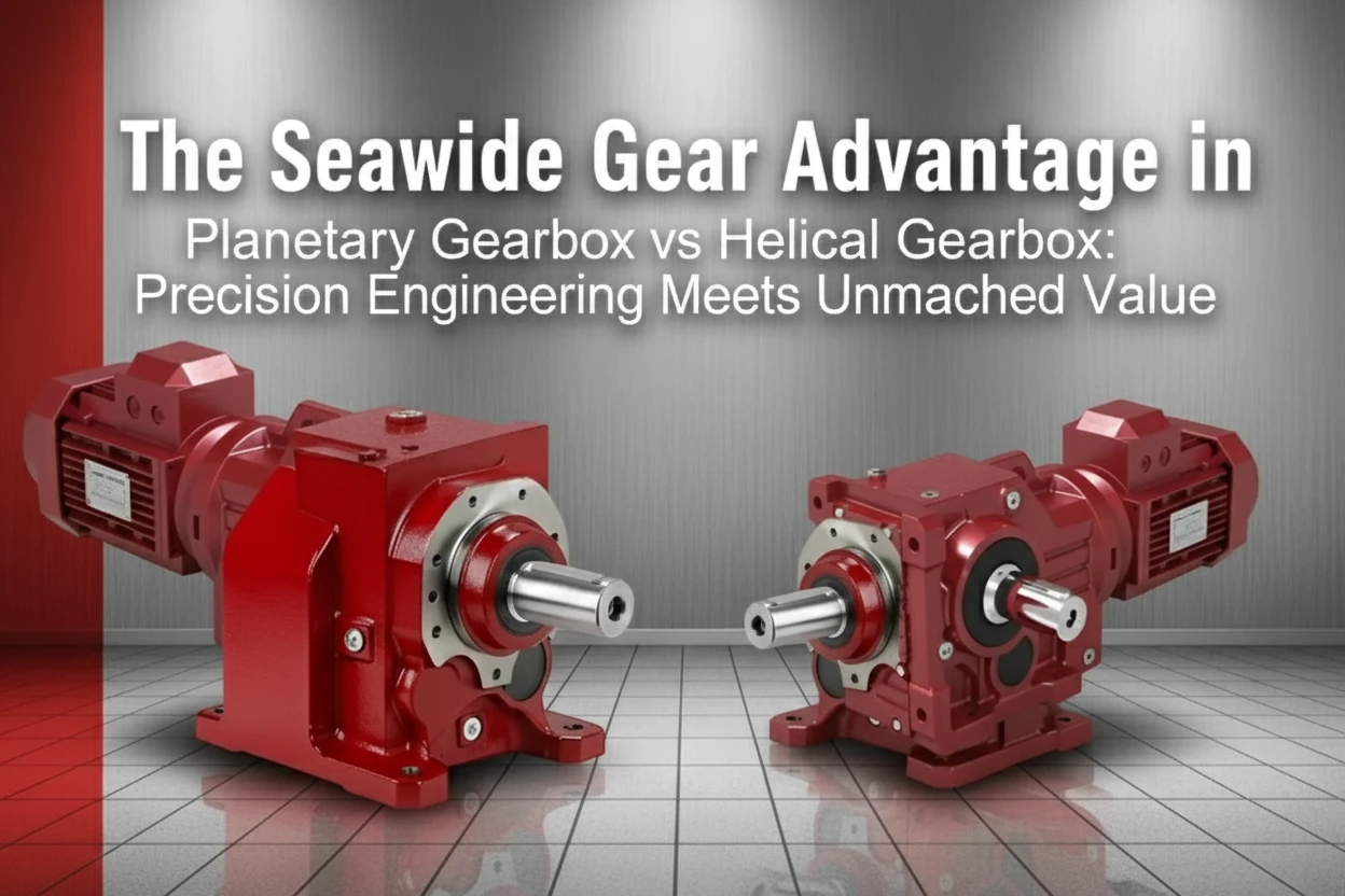
The Seawide Gear Advantage in Planetary Gearbox vs Helical Gearbox Performance: Precision Engineering Meets Unmatched Value
In the competitive global market for industrial automation components, performance must be balanced with fiscal responsibility. While engineering excellence demands the best available technology, budget constraints often dictate compromise. Seawide Gear has systematically dismantled this necessary compromise by focusing engineering resources on optimizing the manufacturing processes for the most demanding gearbox technology: the planetary gearbox.
Why Choose Seawide Gear for Your Planetary Gearbox Needs?
Our philosophy is rooted in the understanding that the mechanical constraints of high-torque, high-precision systems are unforgiving. We specialize where complexity is highest, delivering solutions that meet or exceed the performance benchmarks of legacy manufacturers while offering transformative value.
Engineering-First Approach: Partnership Over Sales
We do not simply sell inventory; we solve motion control problems. Our engineering team engages deeply with your application’s duty cycle, stiffness requirements, and thermal profile. This partnership ensures that the specified reduction ratio, frame size, and materials are perfectly matched to your unique operational demands, whether you are designing a new production line or retrofitting legacy machinery.
Unbeatable Torque Density
The core strength of the planetary gearbox is maximized at Seawide Gear. Through advanced gear tooth profiling, proprietary heat treatment processes, and precision planetary carrier balancing, our units deliver a torque density that consistently outperforms comparable frame sizes from traditional suppliers. This means you can often step down one frame size when specifying a Seawide planetary gearbox compared to a competitor’s, directly translating to lighter, smaller, and more cost-effective downstream machine designs.
Superior Cost-Efficiency: Premium Performance at a Market Advantage
Leveraging optimized global sourcing, high-automation manufacturing lines, and streamlined internal processes, Seawide Gear has engineered substantial savings into the production of high-precision planetary gearboxes. We consistently deliver premium performance—validated by rigorous testing protocols—at a capital investment level that is often 30% or more below what comparable specifications demand from established legacy brands. This efficiency allows our partners to invest capital in other critical areas of their machinery development.
Reliability for Heavy-Duty Applications
The perceived complexity of planetary systems is often met with hesitation in heavy-duty sectors. Seawide Gear has proven its durability through deployments in demanding environments—from heavy machine tooling to high-cycle material handling. Our commitment to materials science ensures that the case hardening and bearing quality withstand the continuous shock loads inherent in industrial processes, making our planetary solutions reliable workhorses, not just precision instruments.
Call to Action (CTA)
Don’t let outdated cost models or preconceived notions about complexity limit your machinery’s potential. Whether you require the ultimate in precision motion control or the highest torque density for a constrained space, compromising on gearbox technology costs you more in the long run through inefficiency and downtime.
Explore our full range of precision planetary gearboxes on our website or contact our engineering team immediately for a free consultation to optimize your power transmission system.
Link: https://seawide-gear.com/planetary-gearbox
Conclusion & Future Insights: Why the Planetary vs Helical Gearboxes Comparison Defines the Next Era of Power Transmission
The journey through the mechanics, advantages, and practical deployment of the planetary gearbox and the helical gearbox reveals a clear engineering truth: there is no singular “best” gearbox. There is only the best fit for the specific parameters of the application at hand.
The helical gearbox remains the indispensable workhorse of industry. Its straightforward design, quiet running characteristics, excellent efficiency in steady-state operation, and competitive initial cost secure its position in the vast majority of standard material handling, mixing, and general mechanical drives. Its robustness and proven reliability in parallel-shaft configurations make it the default starting point for any general industrial speed reduction need.
Conversely, the planetary gearbox is the high-performance enabler. When the constraints involve severe limitations on size and weight, or when the requirement for positional accuracy (low backlash) is non-negotiable, the epicyclic gear train offers a level of power density and precision that parallel-shaft configurations cannot economically match. It is the technology that pushes the boundaries in robotics, aerospace actuation, and high-end machine tools.
By thoroughly understanding the trade-offs—the compactness of the planetary versus the simplicity of the helical, the precision of the former versus the acoustic performance of the latter—engineers are empowered to build machinery that is not only capable but optimally designed for its intended mission profile.
At Seawide Gear, our focus is on delivering the critical edge required in the most demanding scenarios. We provide the engineering expertise and the advanced manufacturing capability to supply planetary gearboxes that redefine performance expectations while bringing operational costs under control. Understanding these fundamental differences empowers you to engineer the future; partnering with us ensures you have the right transmission solution to build it reliably and efficiently.