A Slewing Drive is an integrated rotational system specifically engineered to provide controlled slow rotation while simultaneously carrying high combined loads. Unlike conventional gearboxes that are designed purely for power transmission, a slewing drive acts as a load‑bearing structural component, combining reduction gearing, bearing functionality, and mechanical interface into a single compact unit.
Slewing drives are typically used where high torque, low rotational speed, positional accuracy, and structural stability are required under demanding operating conditions.
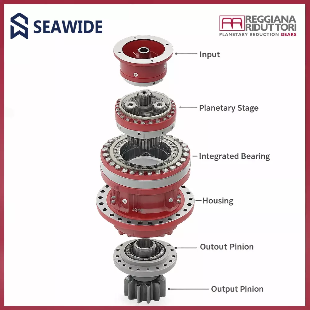
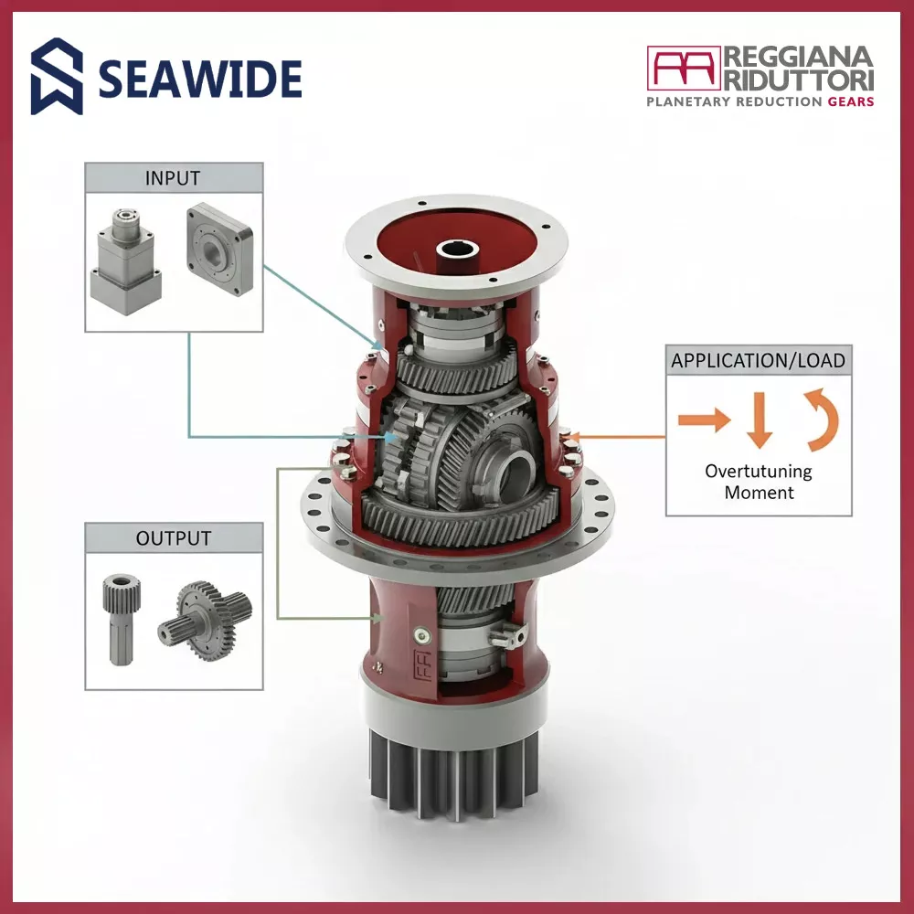
A planetary slewing drive performs three critical functions within one assembly:
This high level of integration simplifies machine design, reduces component count, and significantly improves overall system stiffness and reliability.

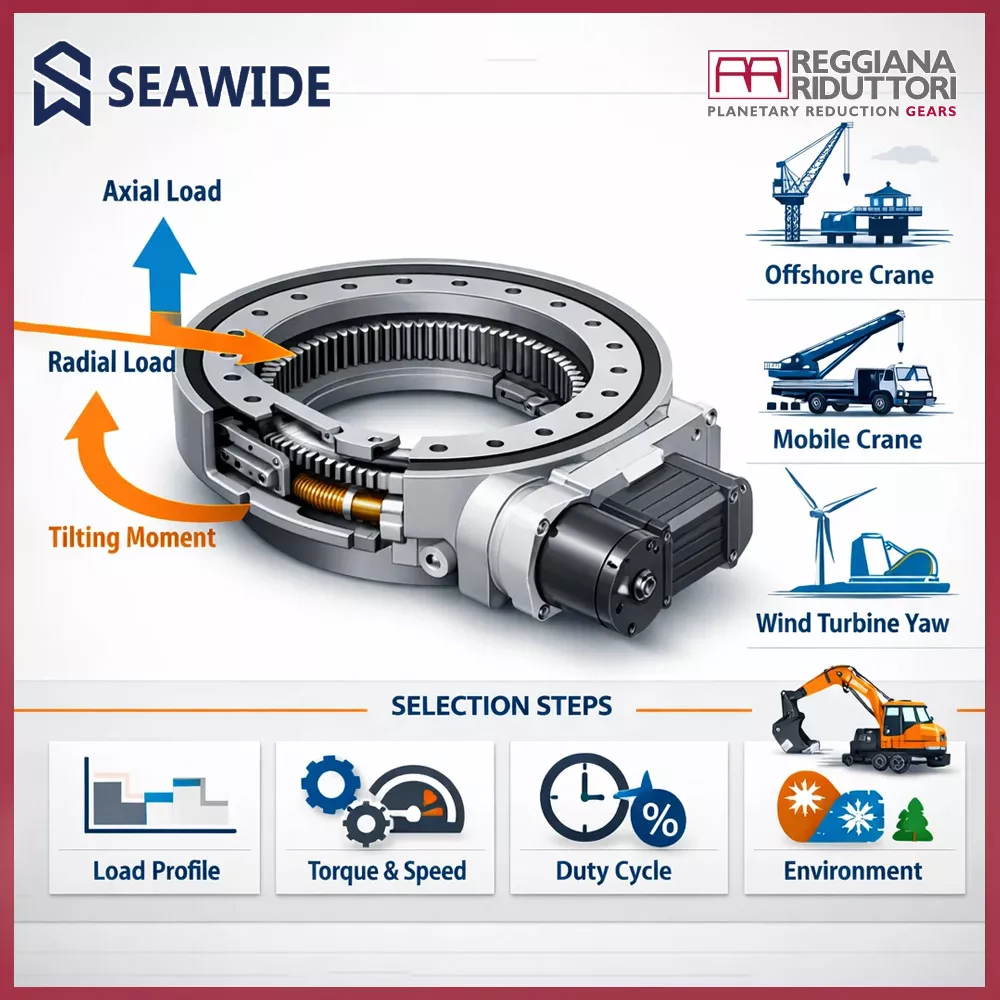
Slewing drives are not selected solely on transmitted torque. Their primary design logic is based on combined load conditions and structural behavior under real operating scenarios. This makes them especially suitable for applications where external forces dominate system performance.
Typical characteristics include:
Planetary slewing drives are widely applied in industries where rotational motion must be both precise and mechanically robust, such as:
In these environments, slewing drives ensure reliable operation under fluctuating loads, harsh weather conditions, and long service intervals.
The key distinction of a slewing drive lies in its system‑level role. It is not merely a reducer added to a machine, but a central mechanical node responsible for motion, load transfer, and structural integrity.
For this reason, slewing drives are commonly available with:
Choosing the correct slewing drive requires understanding not only torque and speed, but also:
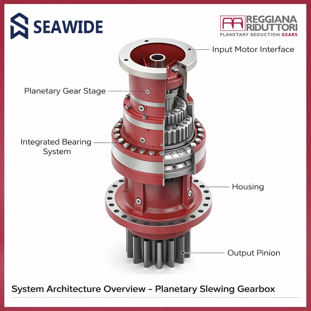
These aspects are addressed in the following sections, starting with System Architecture Overview and Load & Structural Role.

A planetary slewing gearbox is a fully integrated mechanical system designed to perform rotation, load transmission, and structural connection within a single compact unit.
Unlike conventional gearboxes, its architecture is developed around load-bearing requirements, not just torque conversion.
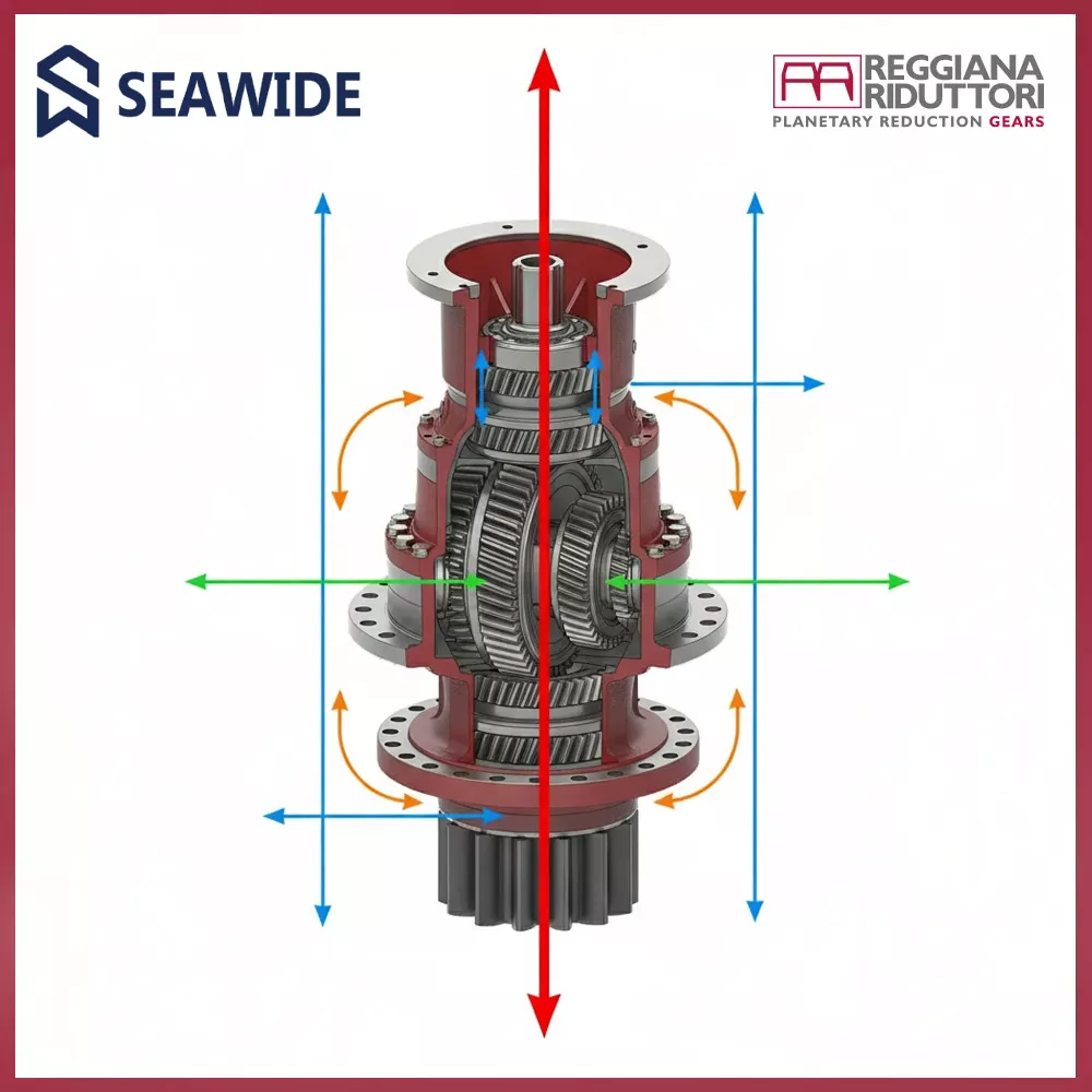
The system is optimized for high torque, low-speed rotation while supporting axial loads, radial loads, and tilting moments generated by large rotating structures.
At the heart of the slewing gearbox lies a planetary reduction stage, chosen for its ability to deliver:
This configuration is ideal for slewing motions where steady torque, smooth rotation, and positional stability are critical.
A defining architectural feature of slewing gearboxes is the integration of heavy-duty bearings within the same housing as the gear train.
This bearing system enables the unit to:
The bearing arrangement directly defines the structural rating of the slewing gearbox and is a primary selection parameter.
The gearbox housing is engineered not as a cover, but as a load-transmitting structural element.
Key characteristics include:
This allows the slewing gearbox to function as a mechanical joint within the machine structure.
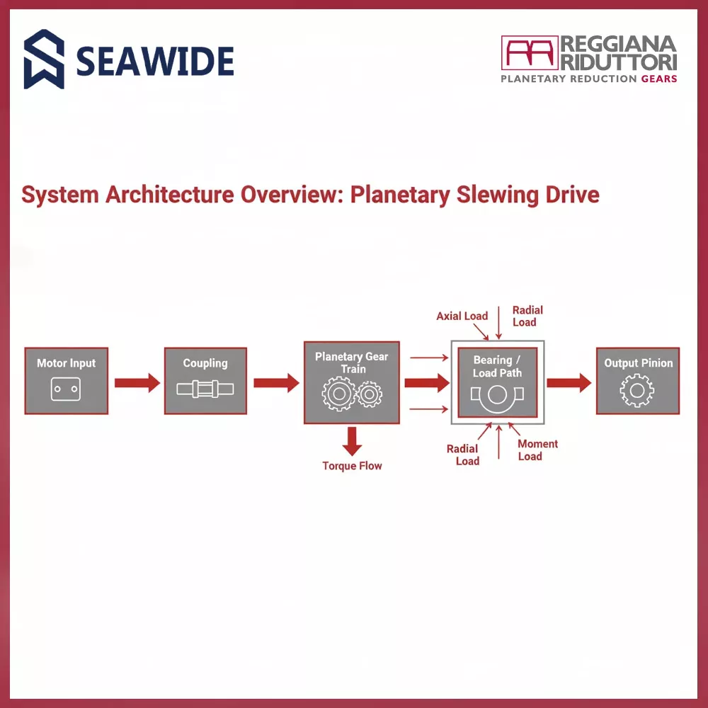
The architectural philosophy of planetary slewing gearboxes is based on controlled load paths.
All external forces acting on the machine follow a defined route:
This separation between load-carrying elements and drive elements is fundamental to long-term reliability.
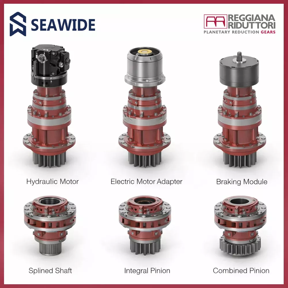
Planetary slewing gearboxes support multiple input configurations to match different drive technologies, including:
This modularity ensures seamless integration into both mobile machinery and stationary industrial systems.
Output Interfaces & Load Transfer
The output side of the slewing gearbox is directly involved in load transfer and may include:
Because external loads act directly on the output, its geometry and bearing support are critical for fatigue life, backlash control, and positional accuracy.
In slewing applications, architecture always comes before numbers.
Before evaluating torque ratings, reduction ratios, or duty cycles, it is essential to understand:
These principles form the foundation for the next sections:
Slewing drives are structural machine components, not simple gear reducers.
Their primary role is to support and transfer combined external loads while enabling controlled rotational motion.
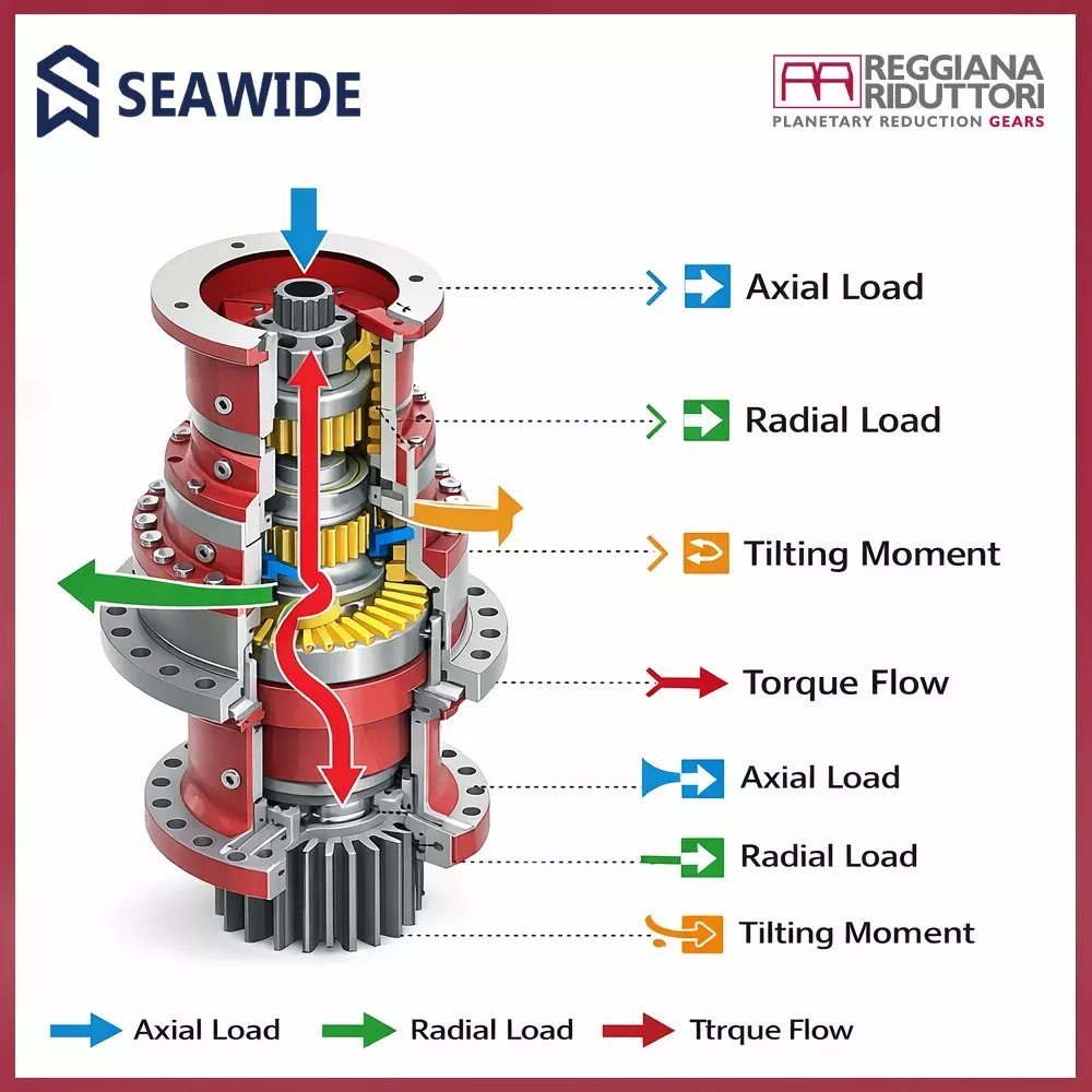
In operation, the slewing drive simultaneously withstands:
The design philosophy separates structural load paths from power transmission:
By acting as the mechanical interface between the rotating mass and the fixed structure, the slewing drive ensures:
This load-centric architecture makes slewing drives essential for applications where rotation, load support, and structural integrity must be combined in a compact, integrated solution.
Slewing drives are structural load‑bearing components, not simple gear reducers.
They are designed to support and transfer axial loads, radial loads, tilting moments, and torque simultaneously within a compact integrated unit.
The core design principle is the separation of load paths and torque transmission:
By acting as the mechanical interface between the rotating superstructure and the fixed frame, the slewing drive provides high stiffness, precise load control, and predictable structural behavior.
This architecture enables reliable operation under heavy loads, shock conditions, and continuous duty, making slewing drives essential for cranes, offshore equipment, wind systems, and heavy industrial machinery.
Slewing drives rely on an integrated heavy‑duty bearing system as the primary structural element, not as an accessory.
The bearing arrangement is engineered to close the external load loop inside the unit, so the gearbox can support the rotating mass while maintaining stable kinematics.
In real slewing duty, the output interface is exposed to combined actions:
The load path philosophy is simple and strict: external forces must not travel through the gear mesh.
Instead:
This bearing‑centric load management delivers:
In short, the bearing set defines how the slewing drive behaves as a structural interface—while the gear train defines how it behaves as a power transmission.
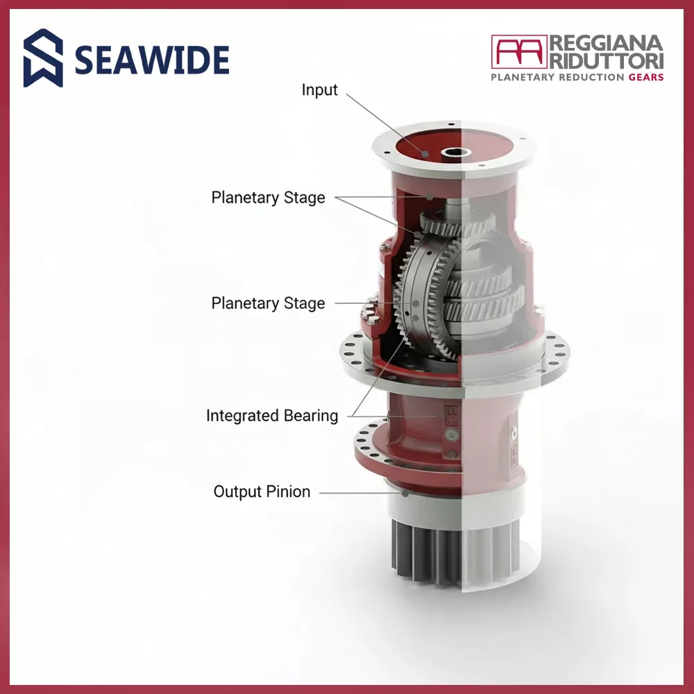
A slewing drive is conceived as a fully integrated unit that combines torque transmission, load absorption, and structural connection in a compact assembly. Its design principle is based on functional separation: the planetary gear train transmits torque, while bearings and housing manage external loads.
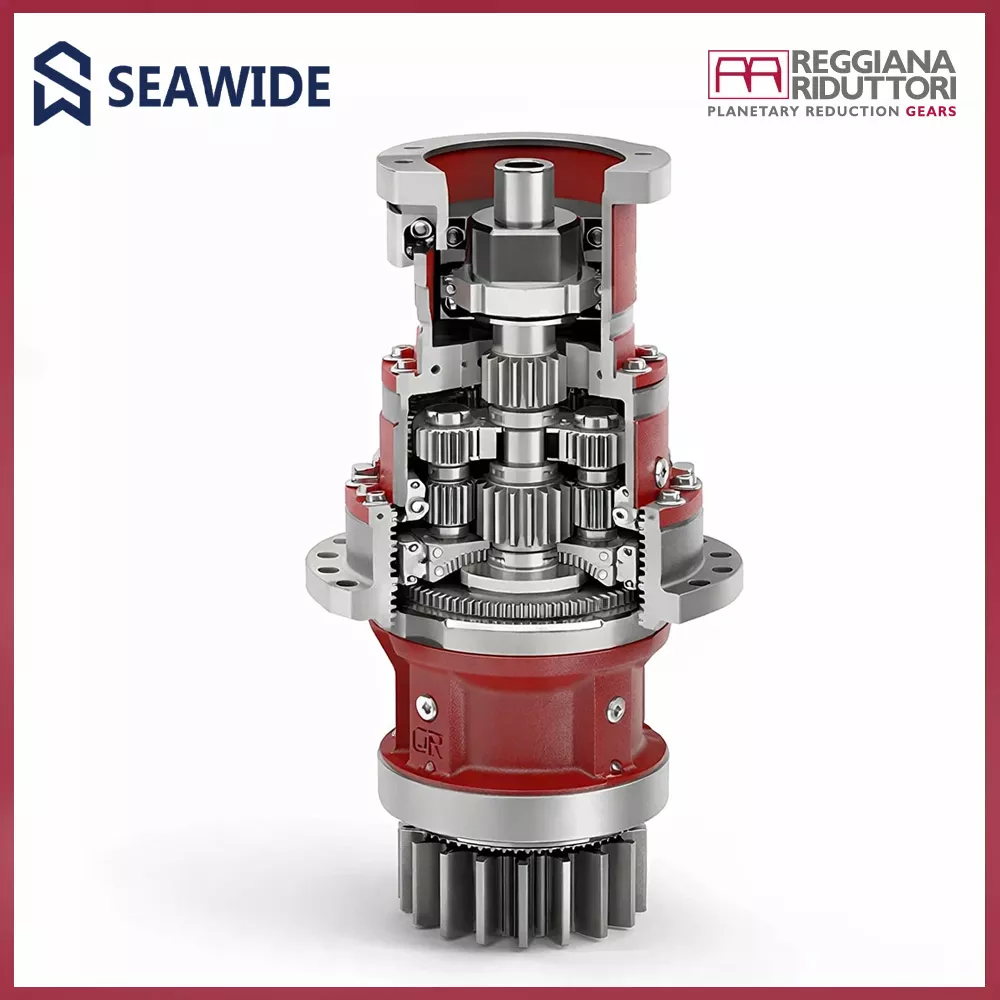
Input power from hydraulic or electric motors is transferred into a multi‑stage planetary reduction system, where torque is increased through load sharing across multiple planet gears. This configuration enables high torque density, controlled backlash, and long service life under low‑speed, high‑load operating conditions.
External axial, radial, and tilting loads are absorbed by an integrated bearing system, which routes forces directly into the housing and mounting flanges. These loads are intentionally kept out of the gear meshes, ensuring that gears operate under torque only, without structural overload.
The housing is designed as a load‑carrying structure, closing the load path between upper and lower interfaces and allowing the slewing drive to function as both a drivetrain and a mechanical joint. Integrated lubrication and sealing systems support reliable operation in harsh environments and intermittent or oscillating motion.
Overall, the slewing drive represents a purpose‑engineered rotational system, optimized for high torque transmission, predictable load paths, compact integration, and long‑term reliability in demanding industrial applications.
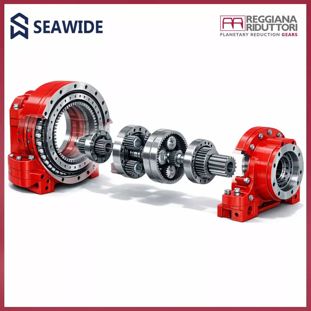
Slewing drives are engineered as modular and configurable units, allowing direct integration into different machine layouts and operating conditions without additional drivetrain components.
They can be supplied with interfaces for hydraulic piston motors, hydraulic orbital motors, or electric motors (IEC / NEMA), with flexible input arrangements such as direct mounting or bevel gear stages to optimize performance and installation space.
Multiple output configurations are available, including splined shafts, integral pinions, or combined solutions, enabling direct connection to gears, racks, or rotating structures. Output shafts are supported by heavy‑duty bearings designed to withstand high axial, radial, and tilting loads.
Optional hydraulically released parking brakes provide secure holding under static or safety‑critical conditions. Lubrication and sealing systems are optimized for harsh environments, low‑speed rotation, and oscillating motion.
The integrated design eliminates the need for external bearings or couplings, simplifying system architecture and improving overall reliability. Certification options such as ATEX and DNV allow use in offshore, marine, and hazardous‑area applications.
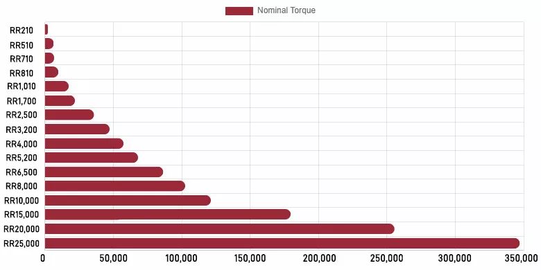
Slewing drive selection is based on a load‑driven configuration logic, where structural loads and required torque define the gearbox size and architecture.
The process starts with defining external loads (axial, radial, and tilting moment) together with the required output torque and reduction ratio. Based on these values, the appropriate slewing size (RR series) and bearing capacity are selected to ensure structural safety and long service life.
Input configuration is then chosen according to the prime mover, supporting hydraulic piston, hydraulic orbital, or electric motors (IEC / NEMA). Output selection—splined shaft, integral pinion, or combined solution—is defined by the driven structure and mounting concept.
Additional parameters such as braking requirements, backlash level, lubrication type, environmental conditions, and certifications (ATEX, DNV) complete the configuration, resulting in a slewing drive fully matched to the application’s mechanical and operational demands.
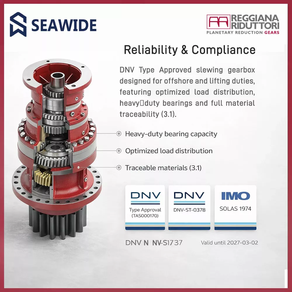
Slewing drives are designed and manufactured in compliance with DNV Type Approval Certificate No. TAS0000170, covering 2000 Series, PLUS Series (planetary) and A Series (bevel) gear units.
The certification confirms conformity with:
Type approval validates suitability for installation on all vessels classed by DNV, ensuring reliability under severe offshore and lifting duty conditions. Gear ratings are defined according to F.E.M. load spectra and utilization classes, with torque values evaluated for lifting appliance requirements.
Manufacturing follows controlled material traceability (EN 10204 – 3.1), verified heat treatment depths, and conservative fatigue criteria based on 90% reliability of survival, supporting long service life and predictable performance in safety‑critical applications.
The certificate is valid until 02 March 2027.